I have a very minor start on this in as much that I have started the power panel.
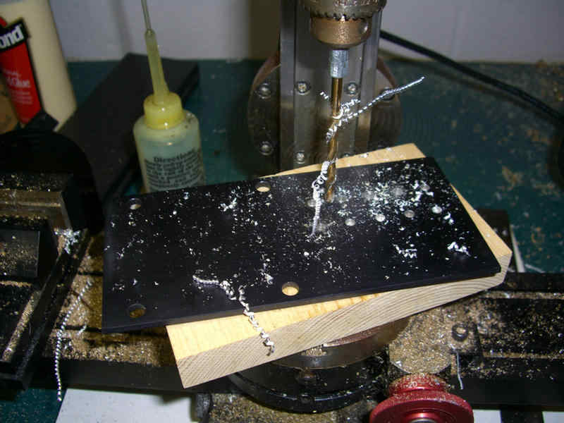
Drilling holes for the pilot lights and switches with the milling machine.
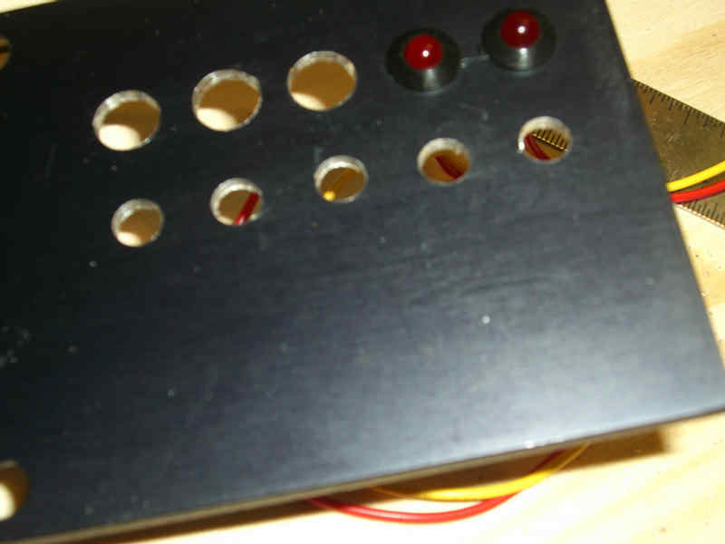
While attempting to place the pilot lights in the plate, I detected a problem. The plate was too thick to let the lights snap into place where they would grip the plate.
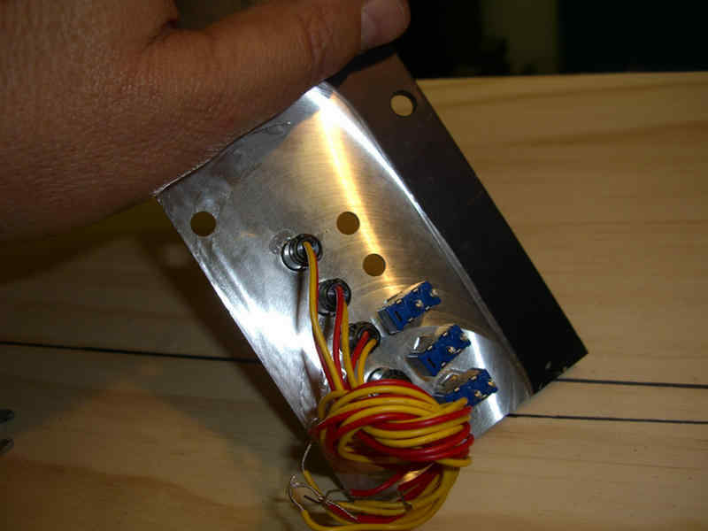
Back to the milling machine and used a fly cutter to remove material from the plate. Now both the pilot lights and the switches fit correctly. More on this later.
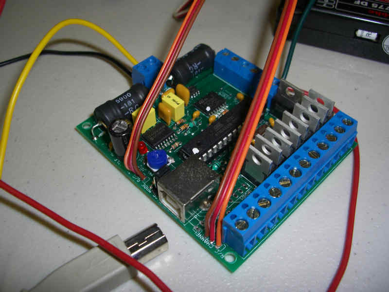
This is the electronic sound system. It has ten different sounds that I will be able to play by pressing one of the buttons on the add-on switch box mounted on the transmitter. I loaded the sounds from the computer. These can be changed to virtually any sounds just by erasing the existing ones and loading others. This board also allows for low amperage momentary, or toggle, switching of 6 additional low amperage devises. More on this later.
Now here is a quick way of making a constant speed reduction motor out of a R/C servo.

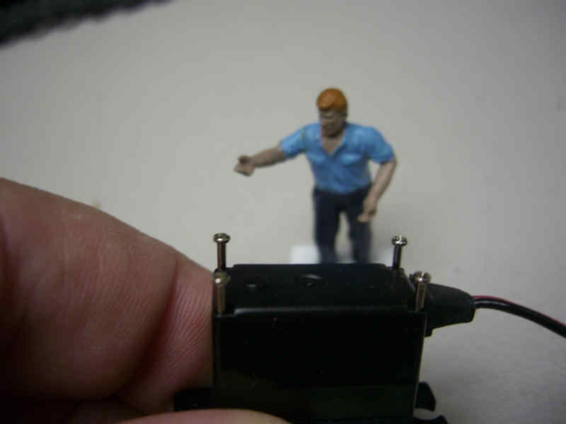
Remove the screws from the bottom of the servo.
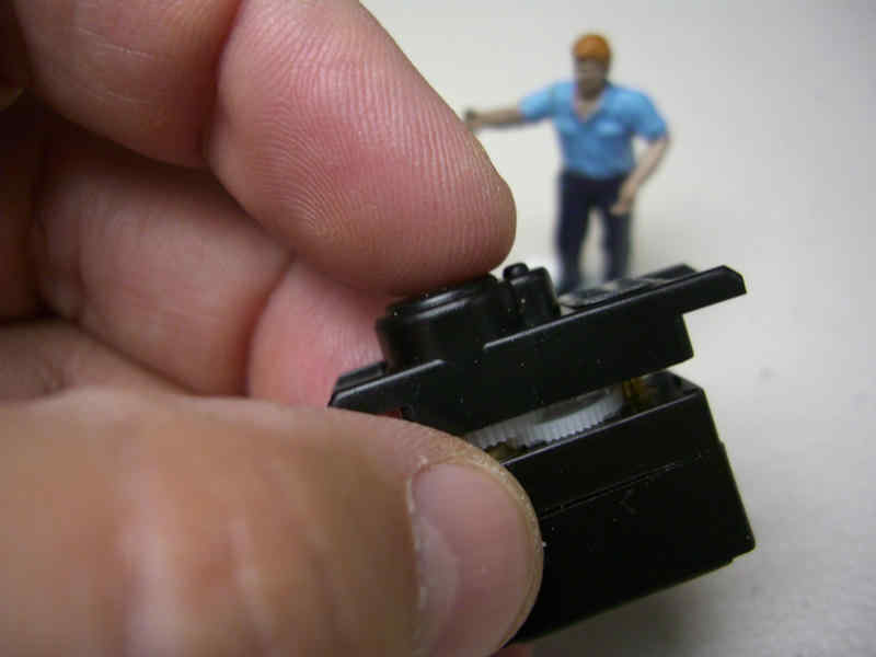
Take the top off being careful not to lose track of all those small gears inside.
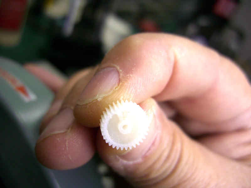
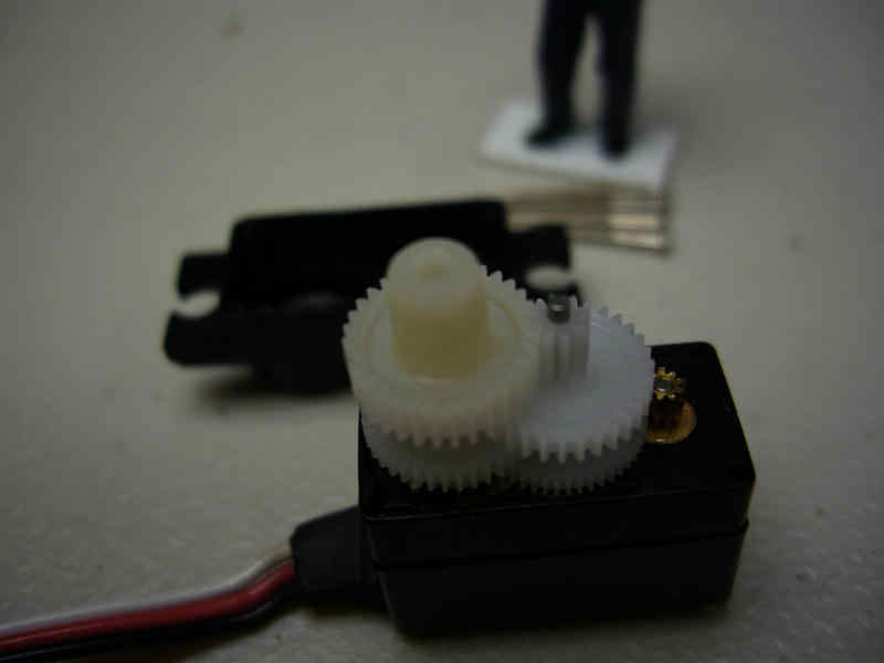
This tab protruding below this gear needs to get cut off absolutely flush with the bottom of the gear.

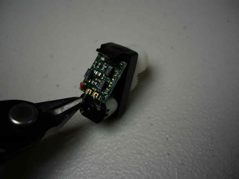
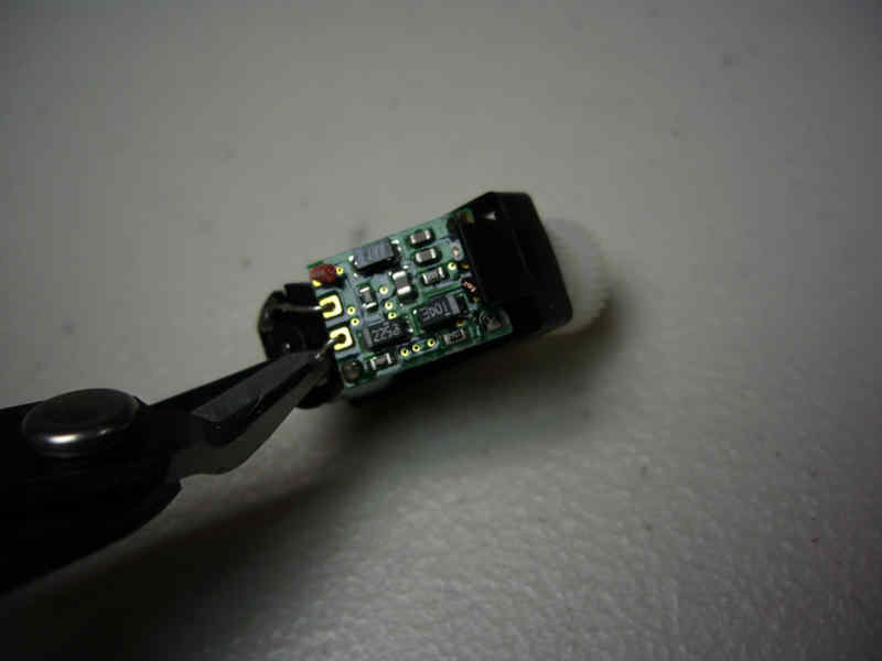
For a constant turning motor, none of the electronics are needed. cut them out and discard them.
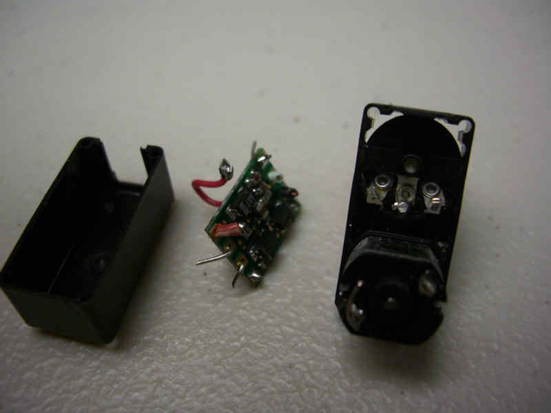
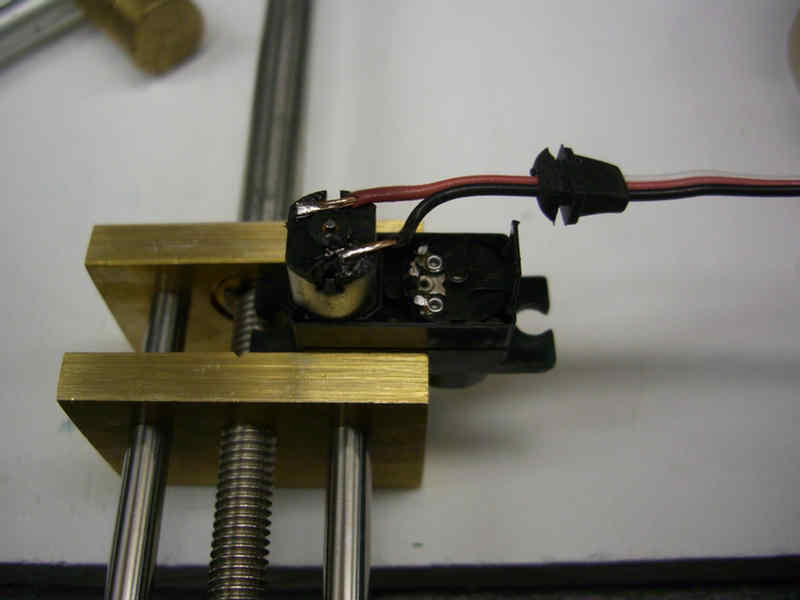
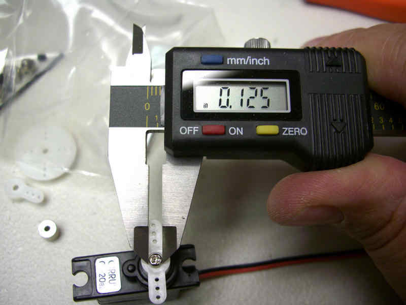
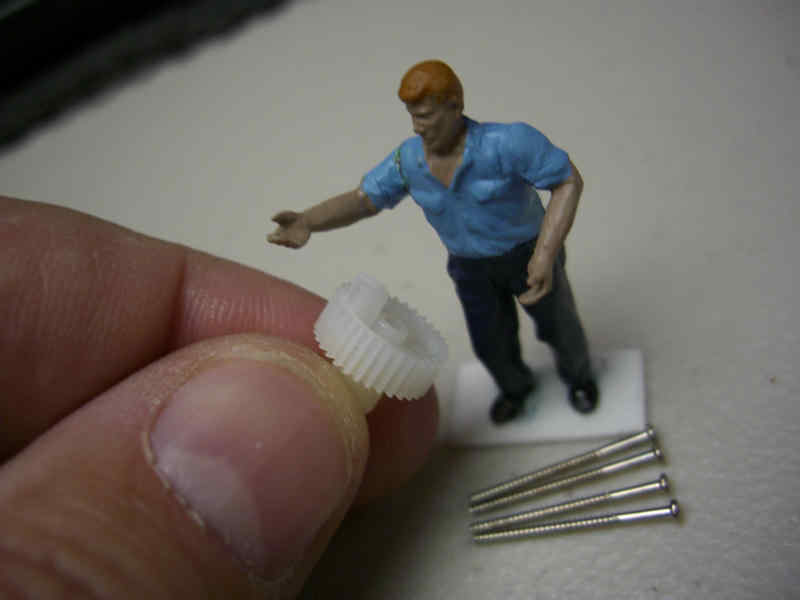
Now solder the two power leads directly to the motor. When you place 3-6 DC volts to these, the motor will turn at a constant speed. I need a collar added to the top of the servo to accept a flexible wire. The head of the screw is larger than the hole in the collar. So, I will measure the screw head and bore only a portion of the collar to allow the screw head to rest inside the collar.
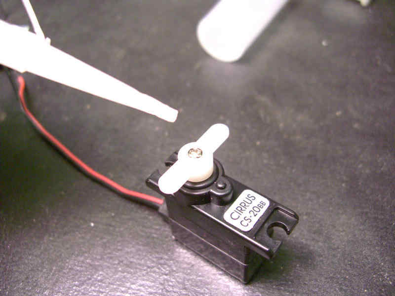
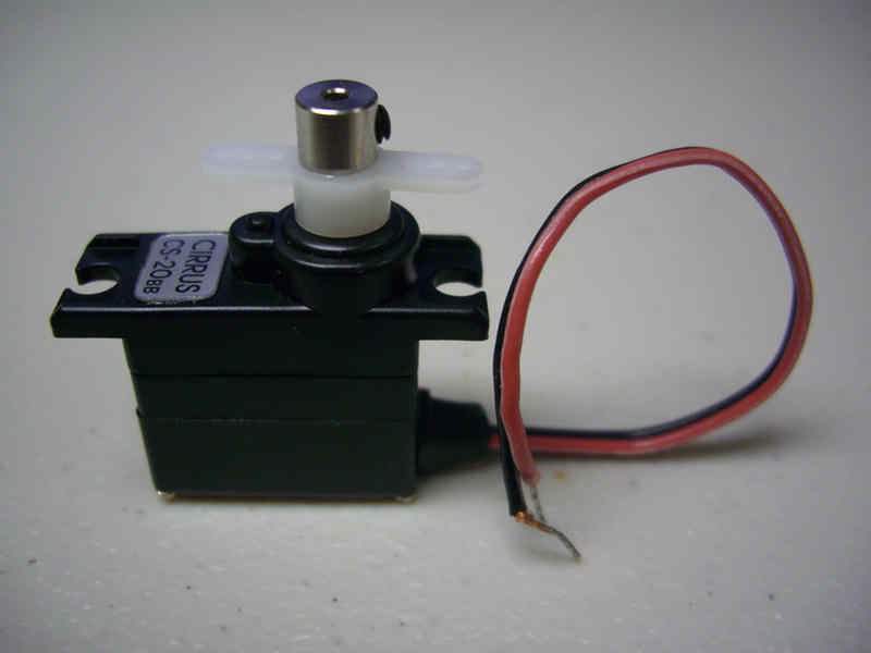
A little C/A and then attach the collar. This geared motor will be used to turn my radar screen at the top of the mast.
On to the power plate.
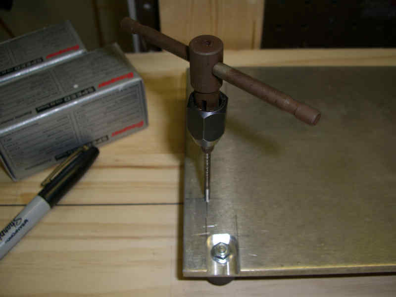
Taping holes for the terminal strips and the fuse block.
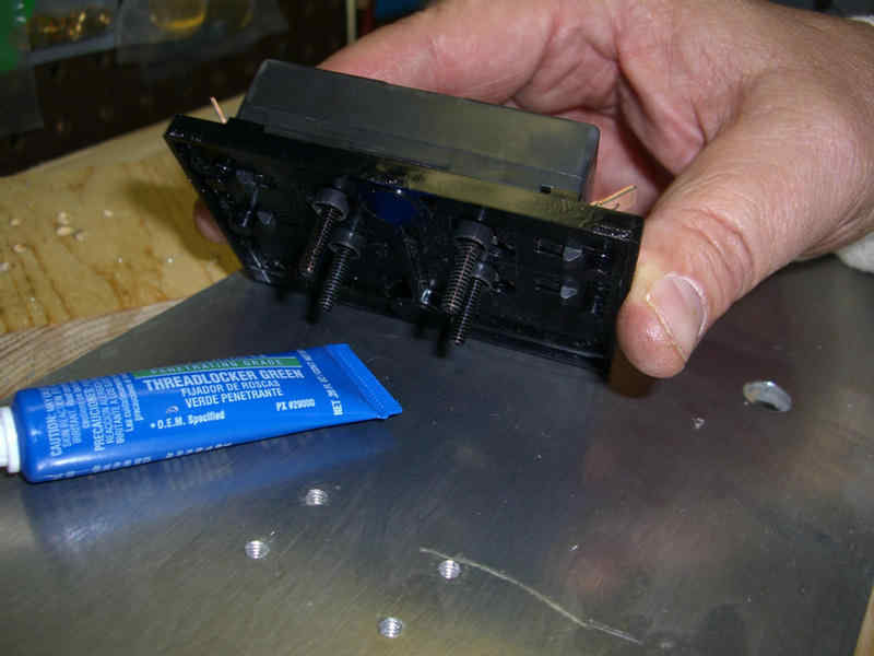
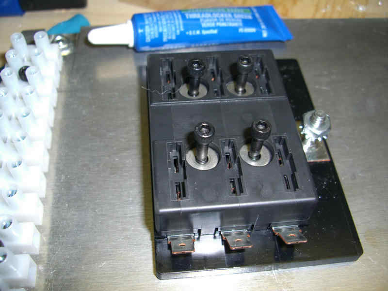
The fuse block being installed using a thread locking fluid on the allen bolts.
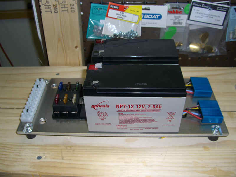
Most of the components in place including the electronic speed controls.
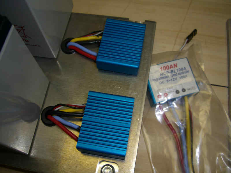
Why three electronic speed controls? One for one motor, one for the other motor, and one more because they are Chinese electronic speed controls. :)
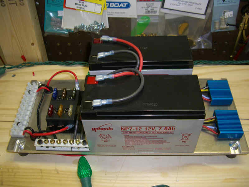
This power plate is pretty much complete and will get set aside.
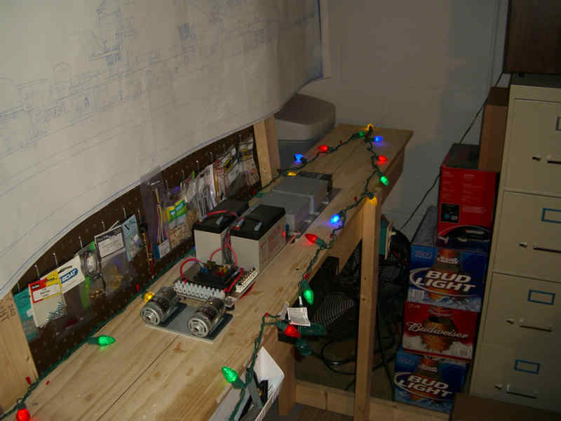
No Hull does not mean I can't celebrate.
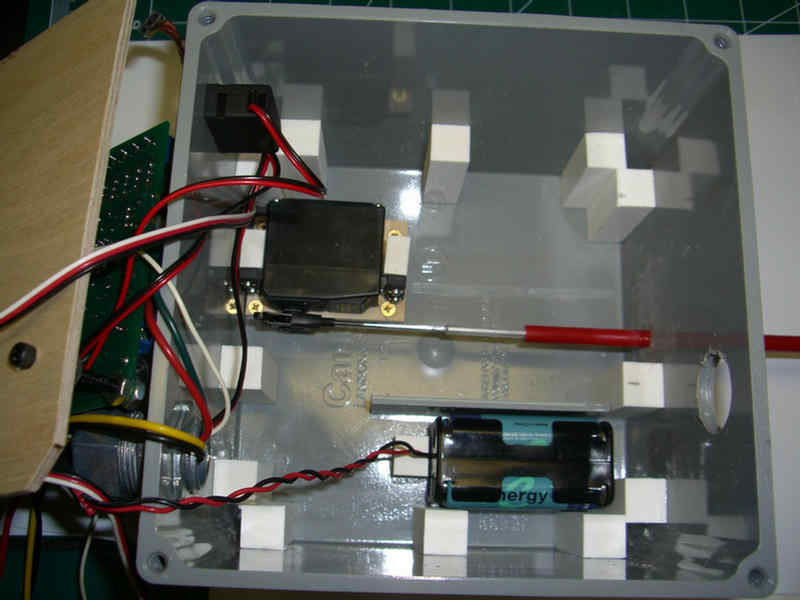
This is my layer cake. Bottom layer is the receiver's battery pack and the steering rudder servo.
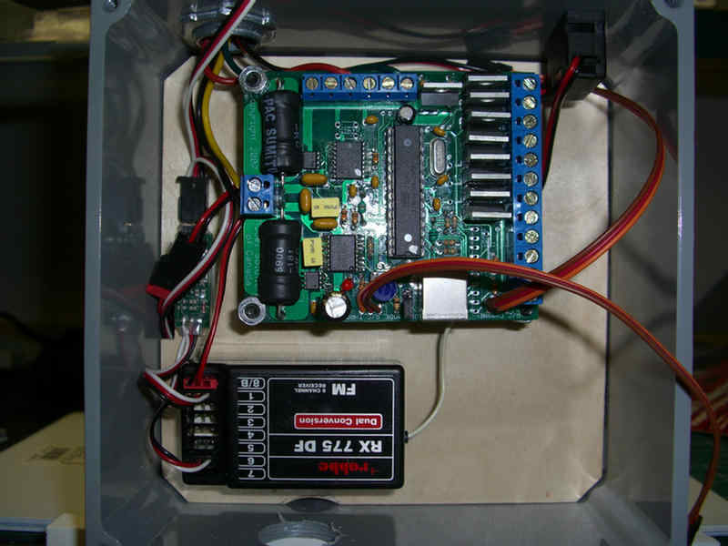
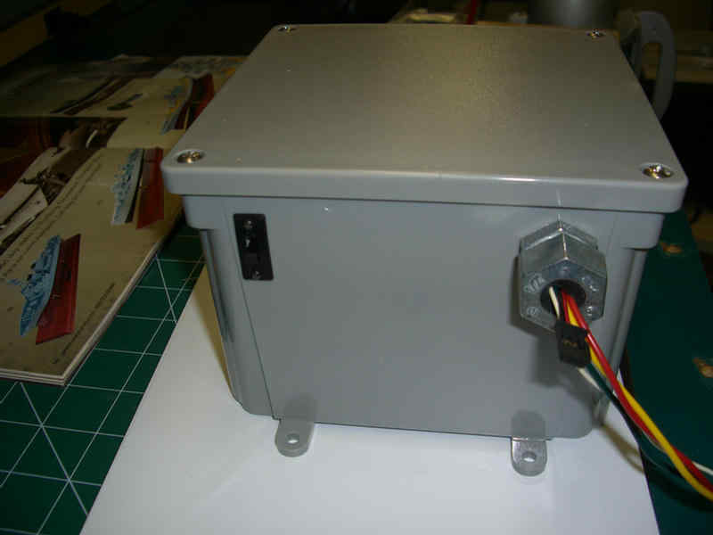
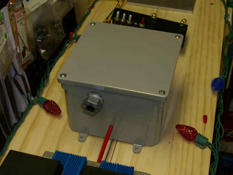
Layer two is my sound card and receiver, all in a water tight container (just in case.)
The red tube is a flexible push rod to operate the rudder. Using this keeps me from having a long electrical extension for the rudder servo. It also prevents interference of the 12v system with the servo signal system. this way I have completely separated the 12 volt system from the receiver and servos.
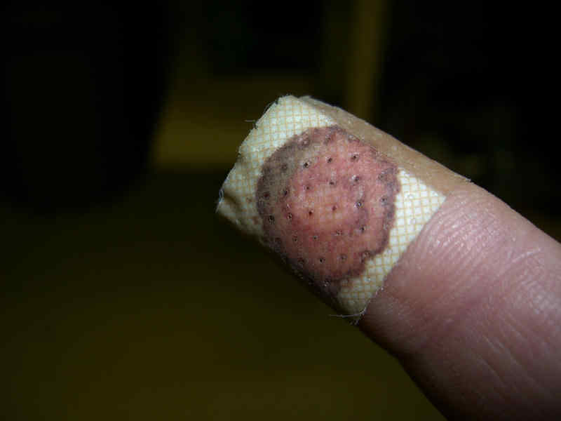
Today's work did cause a boo boo though. However, how I did it was far too stupid to think that I could share how I got it. Thank goodness the 'Lil Wanker wasn't around to see it or he would have had a field day with me.

Ahem....New addition to shop.....
Well, it's been a couple of weeks with little to show. Last week I went to an exhibition called Cabin Fever. It is a model engineering show. That was Saturday and Sunday I had to go out of town. So, it is a week later and Saturday was "Install all the appliances day." Today, I am back on track. A little.....
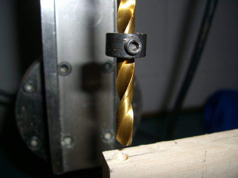
The use of these collars allows you to set the depth of the drill. In this case, I did not want to drill all the way through the wood block.
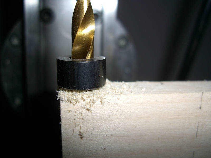
The collar stops the drill from going too deep.
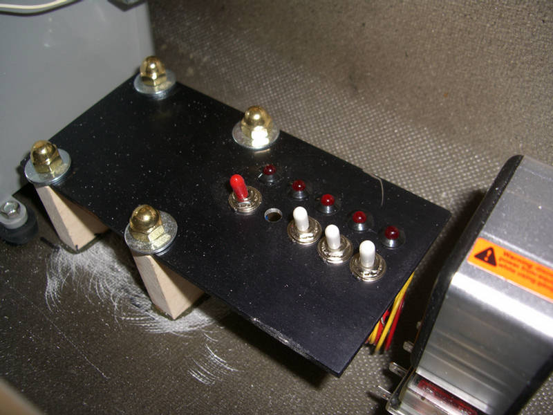
Here is the switching station mounted to the hull. I'll get some nice brass washers to match the brass acorn nuts.
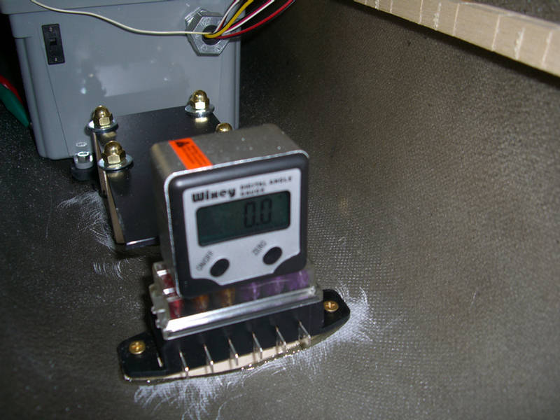
Her, I am installing the auxiliary fuse block. Note the electronic digital level indication I have installed the block level.
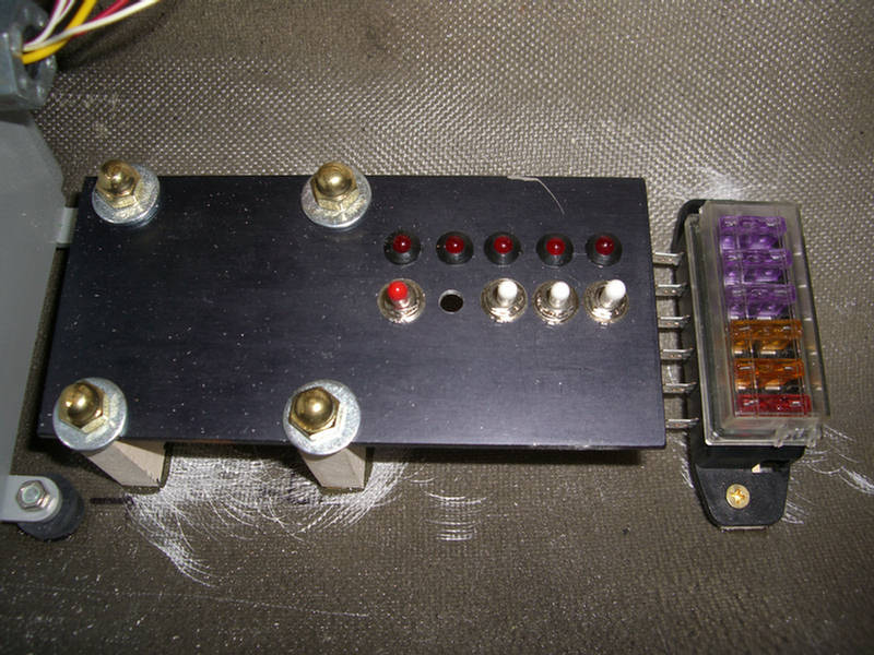
Both the auxiliary fuse block and the switching station installed.
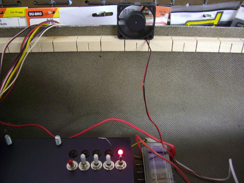
It's ALIVE!! One of the fans on with indicating LED light.
I also got the sound card working today. Now sounds play as clear as a bell just by a push of a button on the transmitter. Even have variable engines sound in both forward and reverse.