I'm tired waiting for the LATE hull. I need to find something to do on it even though it isn't here.
So. I will start with the perimeter beams. One thing I want in my ship is GOOD access to the inner workings. I have spent many a night thinking about how I will accomplish this. I think I have it, so now there is nothing left but to try it out to see if it will work. I plan on having two perimeter beams where many ships have only one. The first one will be secured continuously all the way around the hull. The second will sit on top the first beam and will have all the deck beams secured to it. This means the whole upper structure and be removed if required. I plan on a 360 degree "O" ring to form a seal between the two beams to keep water out of the hull.
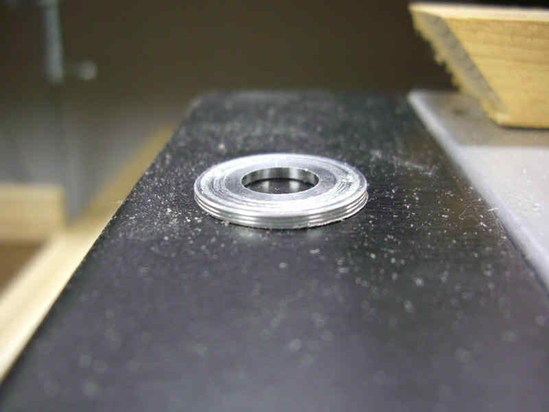
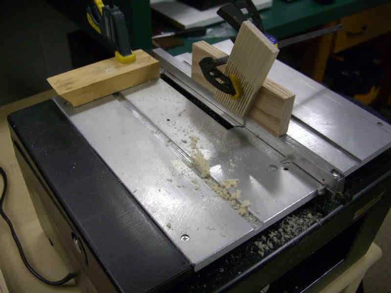
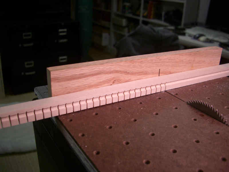
This is a little "dado" washer that is cut on an incline. When installed the saw blade leans at the same angle as the washer. Different washer angles allow for different widths of the dado cut. I chose a 1/16" incline washer to allow for a 1/8" wide dado cut. The photo on the right shows the saw setup to cut the dado in multiple strips of wood.
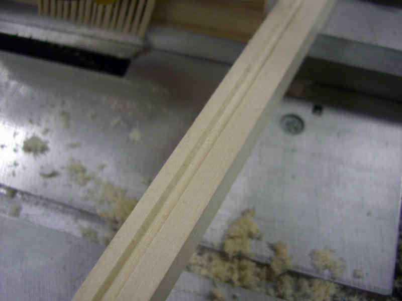
Nice dado cut to accept the o-ring. And, no blood on the table!!
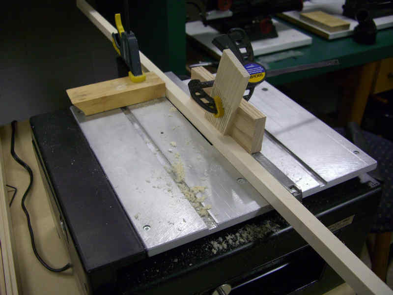
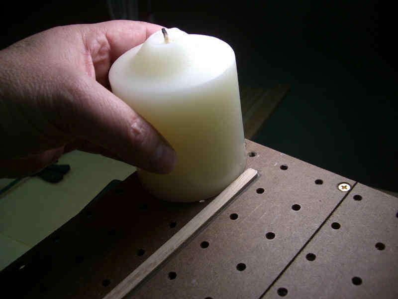
Wood typically doesn't bend very far before you hear the familiar "snap." My destroyer has a serious radius at the fantail, and more curvature throughout its length. To make the wood conform to these different radii, I need to place cuts almost all the way through the wood perimeter beam strips. Closely placed for tighter radii and spaced further apart for more gentler curves.
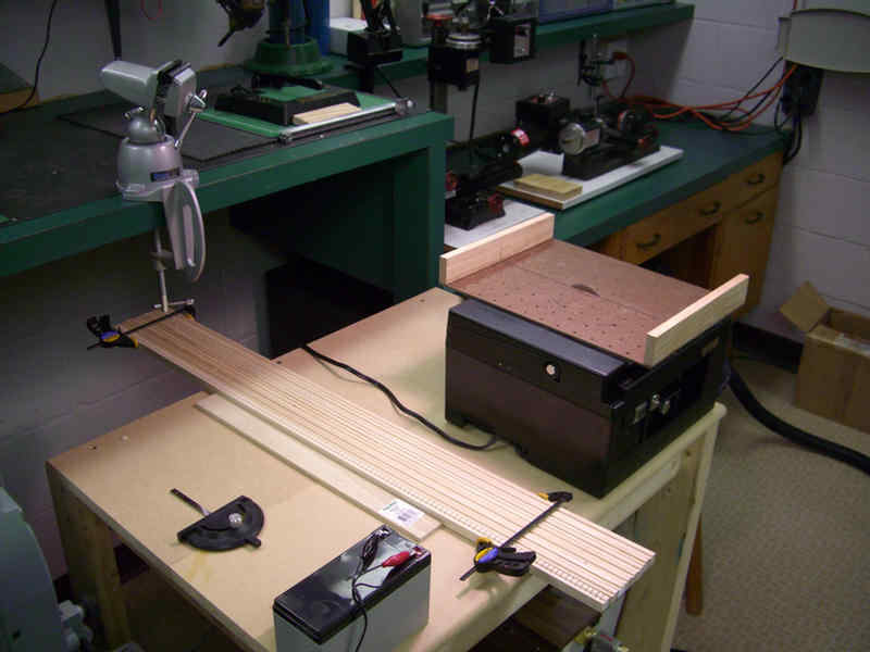
First I need to fix my sliding table. It sticks, ever so slightly, as I traverse it across my little table saw. Here is how I fixed it. Shsshh, MUMS the word now, don't give up my source for fixing it!!!
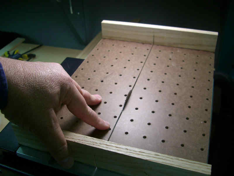
Smooth as silk and it smells "way better" than I ever thought it would.
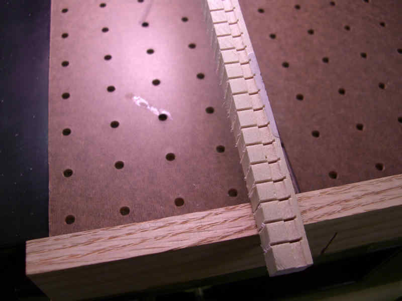
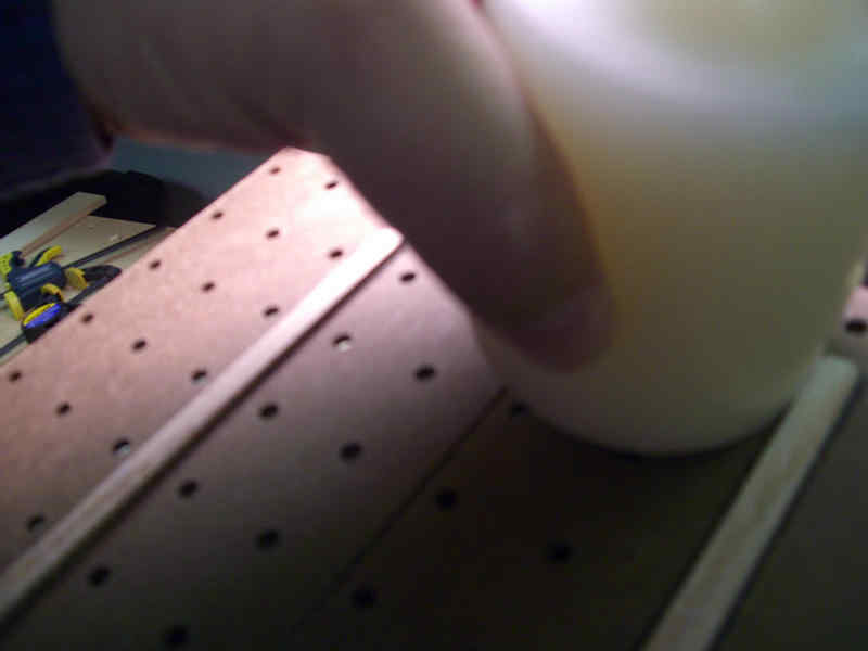
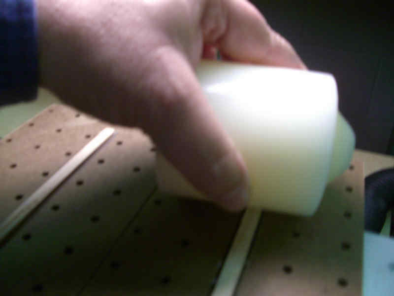
Kind of repetitious, but it went pretty fast with the sliding table calibrated for cuts at 1/4" apart.
CLICK !!
Okay... It has been about an hour. Now I am waiting for the hull again!!!
Next, I am starting the base plate that will be rubber mounted to the inside, bottom of the hull.
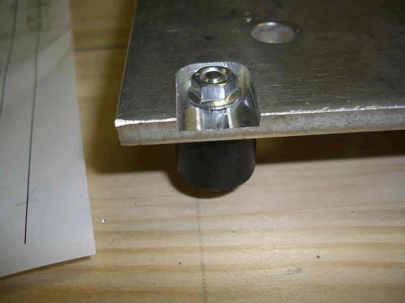
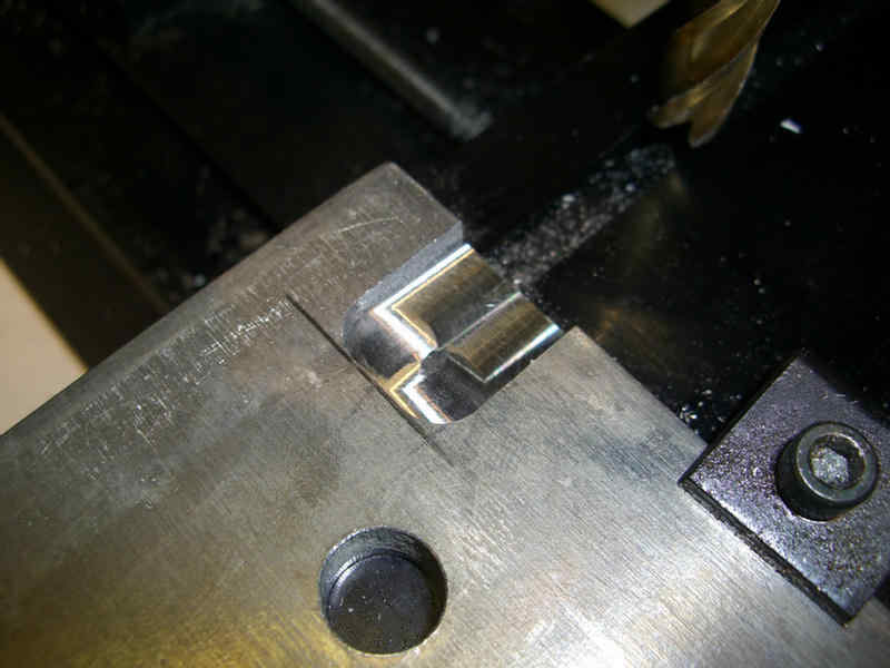
The plate is far heavier than required, but I have several pieces of this size aluminum plate so I may as well use them. The bolt length sticking out of the rubber mount was too short. So, I machined the plate in these areas to allow the rubber isolator mounts to be bolted to the base plate.
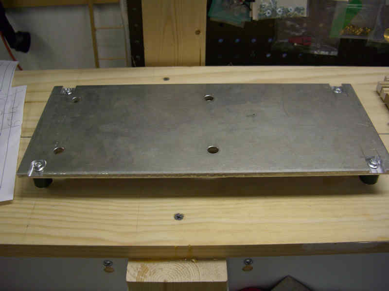
Ready for some electrical gear!!!
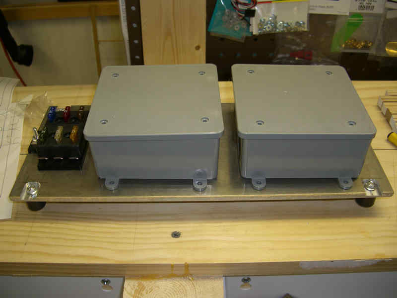
Not sure what my final layout will be yet as I have to see how things will fit in the:
EVER ELUSIVE HULL !!
One thing I want to achieve though is a clean and neat inner workings of my ship.
OMG!!! THE HULL SHOWED UP TODAY!!!! (12-27-07) Only a month and a half to two months late depending on which finish date one uses. Some items still on back order, but they are not required for some time. Having the bare hull will allow me to now make some real progress. I hope the items that I have already built will fit.
The hull has to be cleaned of oils and release agents. If the hull were here in time, I would have done this outside. Now, I had to resort to....................
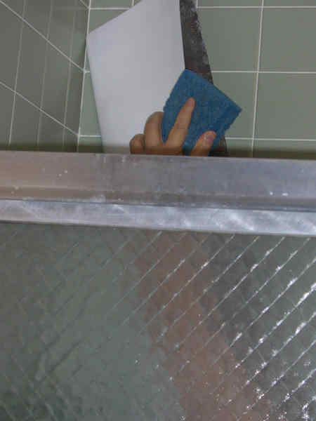
Taking a shower with it!!
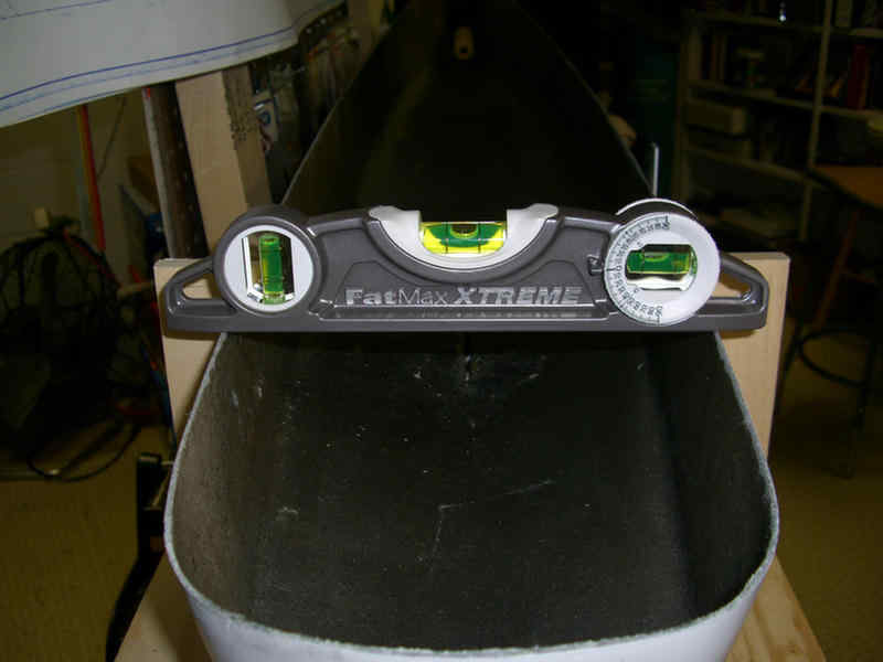
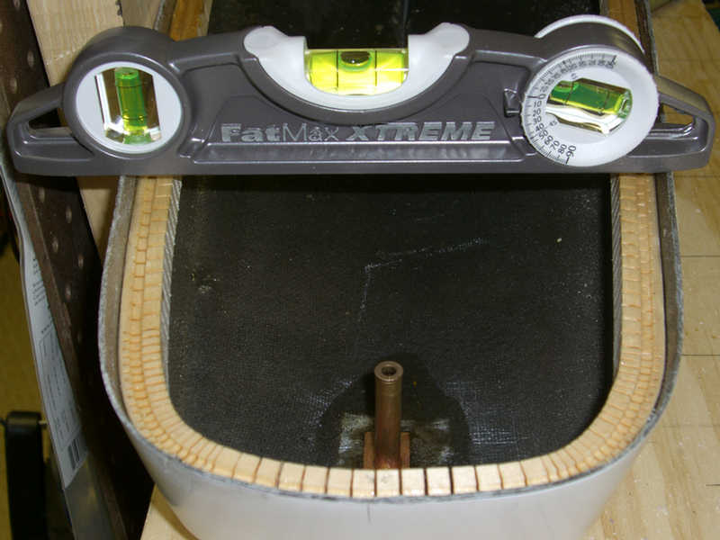
Now that we are both dried off, I need to make sure the hull is level, and flat. I found it has a slight twist which is not uncommon for a long and thin fiberglass structure. The twist will be easily removed when the hull inner reinforcing is added.
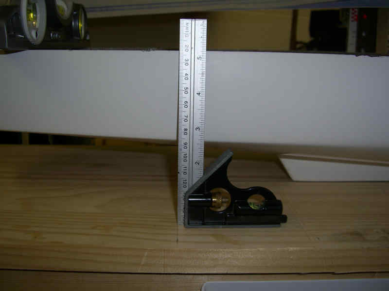
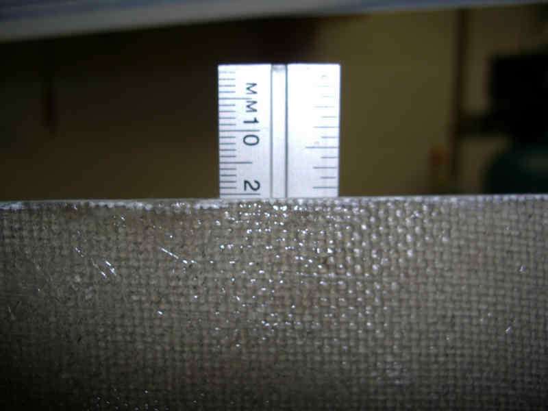
This portion of the hull is level port to starboard. I will secure the hull at this point and check further forward.
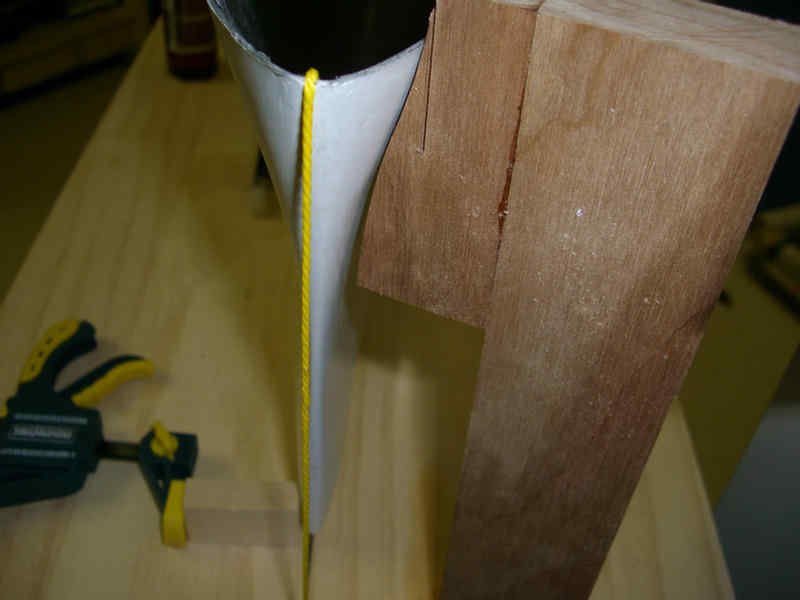
At the bow, I have a plumb bob hanging. The wood stop on the right keeps the top of the bow in place. The clamp on the left has been reversed to allow it to push and hold the bottom of the bow in place to remove the last of the twist.
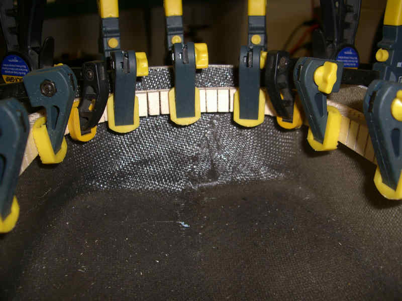
The inner reinforcing ring is being added.
Continuing with the inner ring reinforcement. Later, this will be Z-poxied to secure it in place.
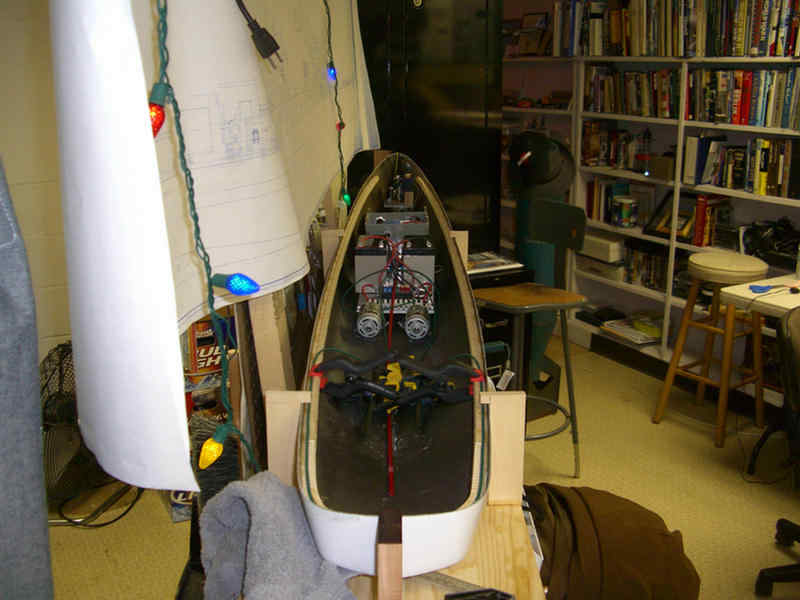
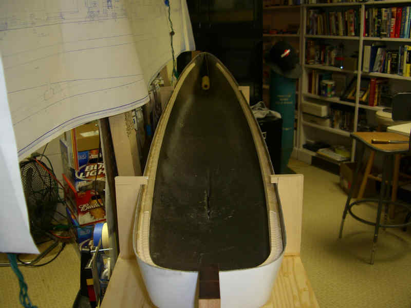
Test fit of equipment. Will need to watch the height on the batteries and the radio box. Now it all comes out until the main deck and hull reinforcements are installed.
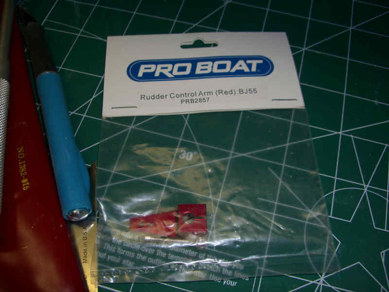
Rudder Assembly
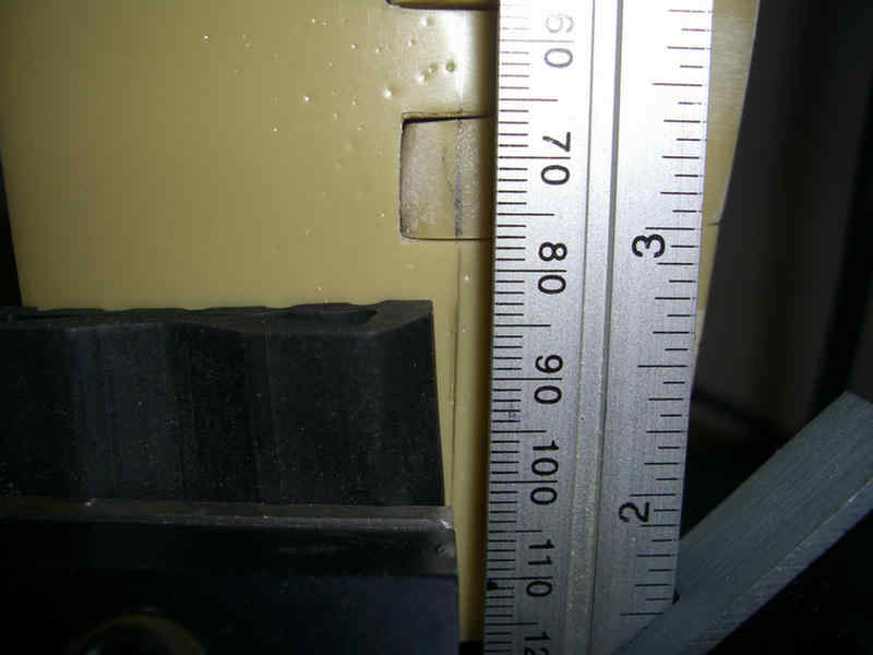
After filing the resin rudder pieces, I then determined the path for the rudder shaft. With jaw protectors in place, I make certain the rudder is lined up in the vertical axis.
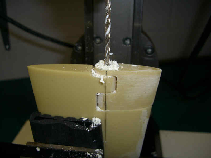
A small pilot hole to insure that the thin resin bosses don't break.
Next is the 3/16" hole that will be used for the rudder shaft.
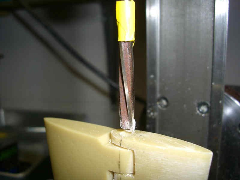
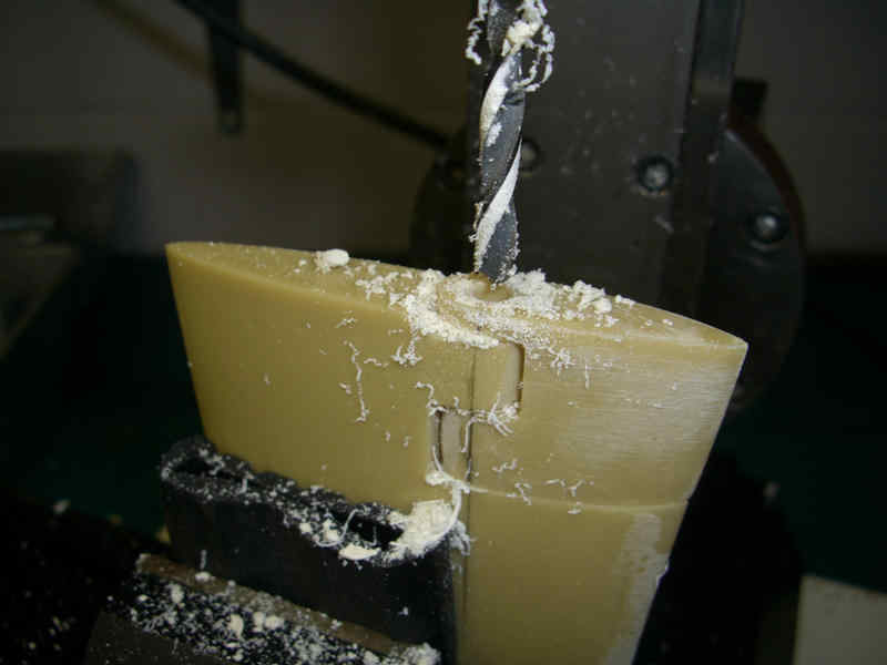
Now a reamer is used just through the first three bosses. This reams the hole out to allow for the brass sleeve forming a brass on brass hinge. Note the yellow tape to warn me of the required depth.
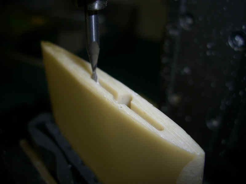
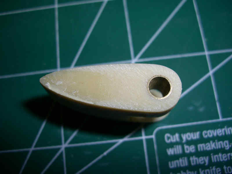
I want the rudder shaft to be removable, so I can't just epoxy the shaft to the rudder. Therefore, I am milling a slot in the bottom of the rudder to allow the rudder shaft to have a drive plate. This allows the shaft to turn the rudder, yet it is removable down and out the bottom of the rudder. The plate forces the rudder to turn with the shaft.
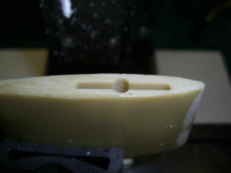
Finished slot for rudder shaft.
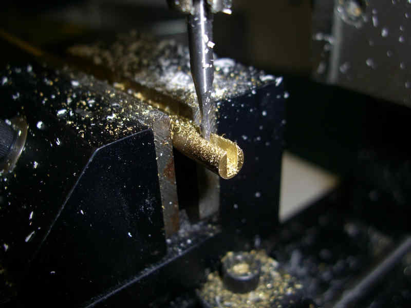
Now I am milling a slot in the rudder shaft to accept the drive plate.
Wanker: Hey pops! You could have done this step with a $2.00 hack saw blade. But then the $500 lathe would have been idle wouldn't it?
Moving right along................
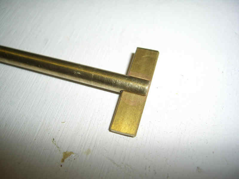
Here is the drive plate just before I silver soldered it to the rudder shaft.
Here are the brass sleeves installed in the fixed portion of the rudder.
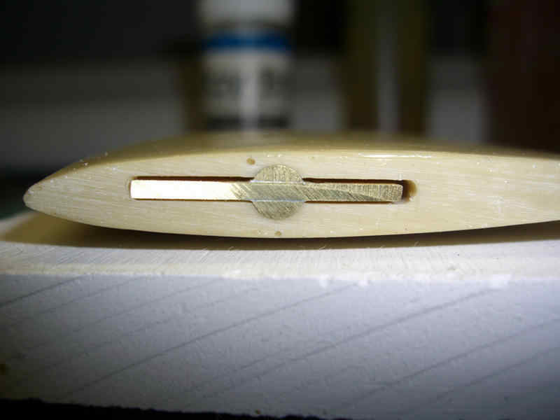
The rudder shaft is installed in the rudder.
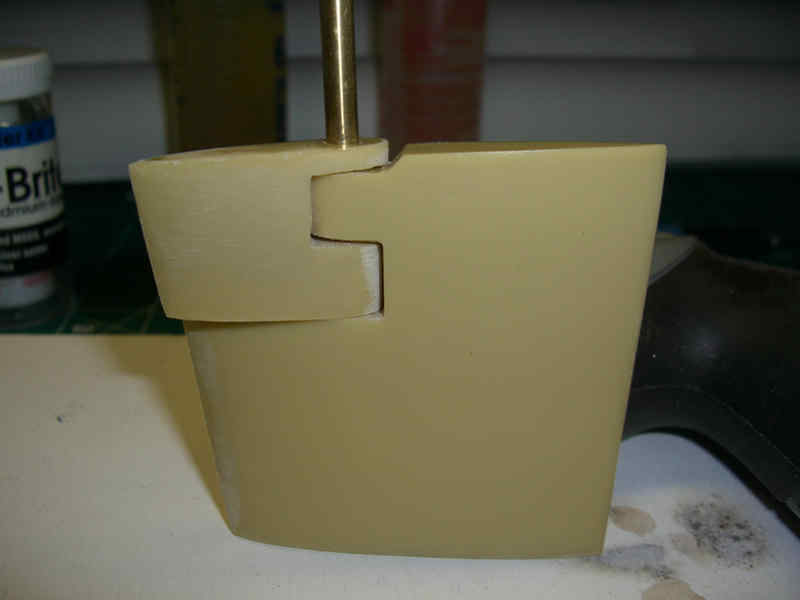
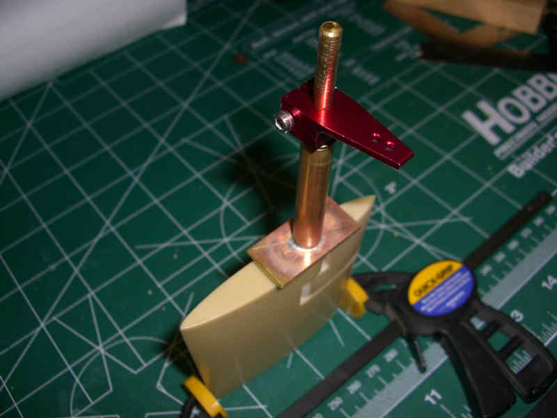
Here is the completed lower assembly.
Some of the items for the inside rudder stuffing tube.
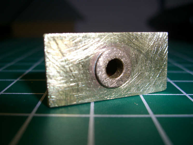
The base plate that will be epoxied to the inside of the hull.
The base plate silver soldered to the stuffing tube.
Red thread locker applied to the inside of the tube to accept the lower bushing.
A little something from the fast boat guys.
Will leave the extra shaft in place until final fitting into the hull. Then it will be cut down to final length.
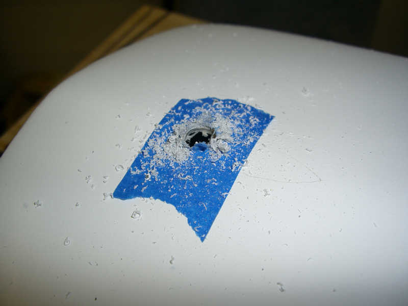
Okay, it's back on the hull after a little time spent with the main deck. The hole for the rudder stuffing tube is located then drilled. Note the masking tape to prevent the chipping of the gel coat on the hull.
Next, the stuffing tube plate is liberally scuffed up to allow the epoxy to grab on to.
The same scuffing is done to the hull. The last thing I need is this rudder stuffing tube to pop off creating a nice hole in the bottom of the ship.
Before we can epoxy the tube in place I have to make sure the rudder will be aligned to the bottom of the hull. I wrapped the rudder in plastic to protect it from any epoxy that might seep through the hole in the hull.
The rudder is now aligned and the stuffing tube can be epoxied in place.
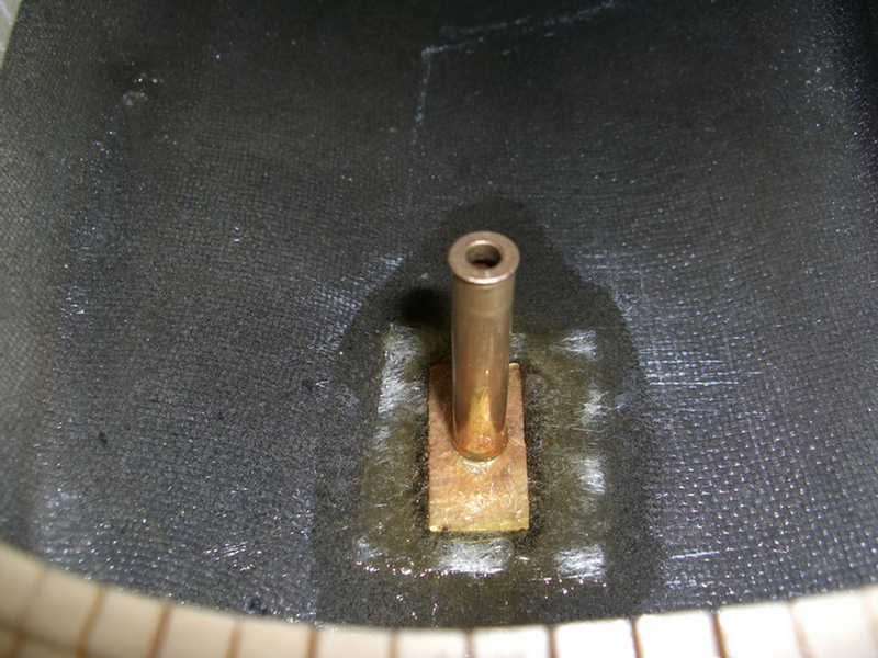
The rudder is now removed and the stuffing tube is securely in place. But to make certain it is there for good, I will mat it in place.
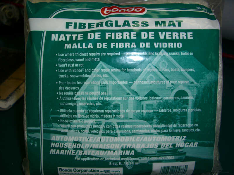
Good 'ole Bondo. This time I will use their fiberglass matting.
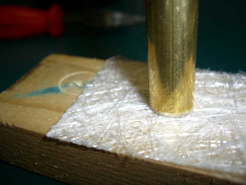
I cut out a rectangle larger than the plate on the rudder stuffing tube. Then I sharpened a piece of brass tubing to become a punch.
Now there is a hole in the mat to allow it to slip over the tube.
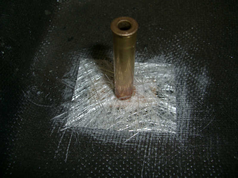
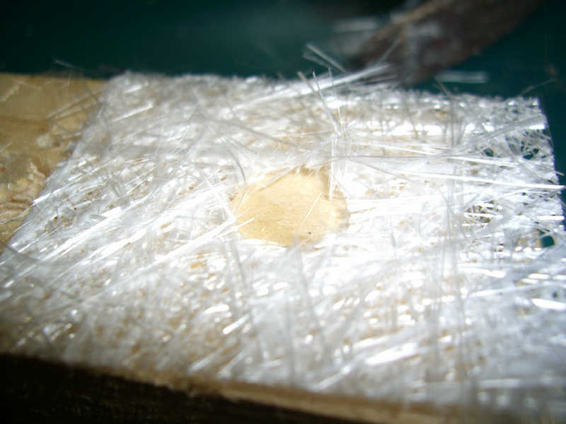
Here is the mat dropped into place.
Once you start dabbing resin or epoxy over the mat it wants to slip & slide around or stick to the brush and lift. Here, I CA'd the mat in several places to keep it in place.
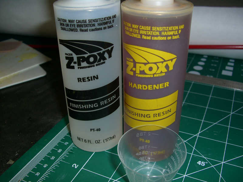
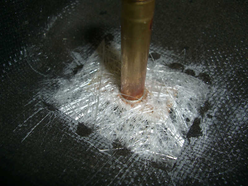
Now it is time to mix up some resin. I love the smell of regular fiberglass resin. My wife hates it. So, I will use "Z-Poxy. It is totally odorless allowing for harmony throughout the land.
Here, I have dabbed the Z-Poxy over the matt, ensuring the rudder stuffing tub remains in place.
Will let it cure and then double check that the rudder remains aligned. (It better be, as I don't want to think about having to remove this tube!)
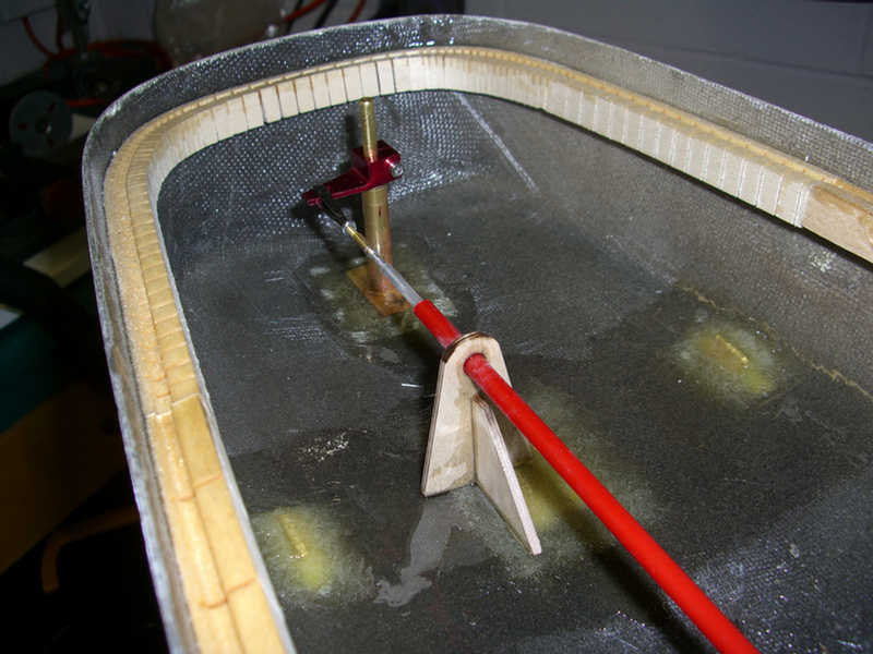
Here, I have made the rear support for the rudder push-pull rod.
Well, this is the extent of my work this weekend. Again, I think I have made good progress.
1. Stuffing tubes built and installed
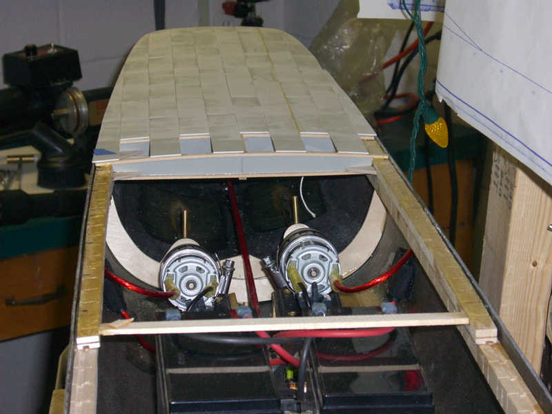
2. Motor mounts built and installed
3. Motors installed
4. Bulkhead built and installed
5. Power plate and radio box installed
6. Anchor winch assembly test fitted to hull